 |
MRIreg:
MRI-to-miniBird Registration |
It is often useful to coregister a MRI scan with the subject's
real head geometry - for example, with Transcranial Magnetic
Stimulation, it is useful to have a precise idea of which region
of the brain is being stimulated. MRIreg is a free tool that
allows you to identify which region of the scalp is near a
particular brain region. To use MRIreg you will need:
- MRIreg for Windows [free, shift+click
here to download version October 2013].
- MRIcro for Windows [free from the MRIcro
home page].
- A MRI scan for the person you want to register.
- An Ascension
Flock-Of-Birds/MiniBird, Ascension trakSTAR, or Polhemus
Fastrak magnetic position tracker.
It is easiest to get good results from coregistration by using
MRI scans where you have marked easy-to find landmarks on the
individuals face or scalp (e.g. place liquid-vitamin gel-capsules
on their facial beauty marks during scanning). You will need to
find at least 5 anatomic landmarks.
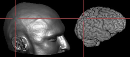
| Start MRIcro, and make sure the 'Yoke' and 'XBars'
controls are checked [outlined in purple on the picture
to the right]. It is generally easiest to find landmarks
in the 'projection' view that shows the Axial, Sagittal
and Coronal views simultaneously [click on the 3D-cube
button outlined in blue]. Load the MRI scan and find your
landmarks (regions that you can identify on both the MRI
scan as well as the individual's head [e.g. bones, nose,
ears, etc]). If there are any anatomical regions of the
brain you wish to locate (e.g. the motor hand area), you
will also want to work out these coordinates. For all the
landmarks, you will want to know where they appear in the
X,Y and Z coordinates (outlined in green). |
 |
Start the MRIreg software. Switch on your Bird and switch it
to 'Fly' when the sftware asks you to. If your Bird is connected
correctly, the XYZ position of the bird sensor should appear at
the bottom-right of the MRIreg window (e.g. 'FOB -742 139 892');
this value should change when the Bird sensor is moved. If this
does not work, try adjusting the serial-port speed (the 'FOB'
menu allows you to choose a speed between 9600 and 57600 baud, as
well as letting you select either a bird or Fastrak system).
Likewise, for Fastrak systems, make sure the tracker on and is
connected to your laptop, and that MRIreg FOB menu is set for the
proper port speed and tracker type.
You are now ready to add in coordinates to MRIreg. At this
point, MRIcro should be displaying the MRI scan, and MRIreg
should be displaying the position of the bird sensor (at the
bottom right of the window) and the MRI scan coordinates (at the
bottom left).
 |
Step 1: Calibration
- With MRIcro, click on the projection view to
select an anatomical position. (You want to
select the location where the sensor will be,
e.g. instead of the tip of the nose, select a few
millimeters anterior to the tip).
- Move the magnet sensor to the location displayed
in MRIcro.
- Press the MRIreg '+' button (or press F1). A new
spreadsheet row appears in MRIreg, showing the
MRI position (left) and the corresponding magnet
position (right).
- Repeat steps 1-3 until you have entered all of
your anatomical landmarks.You must enter at least
5 positions, more positions give better accuracy
during magnet tracking. Pick well-separated
points (e.g. select regions on the face, the
ears, the back of the head and the top of the
head; instead of only points on the face).
|
Step 2.Magnet Tracking
- Once you have entered all of your anatomical
landmarks in step one, press the 'correlation
line' button on the bottom left corner of MRIreg
to switch from calibration to tracking mode. This
will have several effects:
- The spreadsheet disappears. In its place
you see the magnet-to-MRI transform
function and the current
magnet-to-desired MRI coordinate
distance.
- The MRI position in MRIcro will now
change depending on the location of the
magnet.
- You can now enter the coordinates of your desired
anatomical target (e.g. the motor hand area) in
the 'desired MRI' boxes. MRIreg will estimate the
current distance of the magnet from this point.
- Note: The magnet-to-target distance is
reported in voxels. For images where the
voxels are not cubic (e.g. 1x1x3mm scans
instead of 1x1x1mm scans), this can be
confusing. Note that the bottom left
shows the estimated voxel positions, so
you can calculate the true distance
yourself.
|
 |
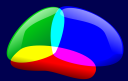
| Magnetic sensor on scalp |
After calibration the location of the
magnet track can be observed: |
Default location of FOB base unit:
all scalp locations within one meter
all scalp locations in single hemisphere of base unit |
 |
 |
 |
Normalization
Normalization refers to strecthing, rotating and warping
brains from different people so that the resulting images are
aligned in standard space. Once an image has been normalized, its
shape roughly matches other normalized images. This allows you to
use Talairach coordinates to describe different brain locations,
and eases making group comparisons. There are two ways you can
use normalization with MRIreg:
- Conduct MRIreg positioning on the raw MRI scan. Then
normalize the image and convert the locations you
stimulated with the same transfroms you applied to the
raw MRI scan. This allows you to describe the locations
you stimulated in stereotaxic space. The advantage of
this method is that you can apply both linear as well as
nonlinear normalization transfroms, so you get a better
fit. However, it is also more complicated.
- Transform a linear-only normalization on the MRI scan.
Use MRIreg with this normalized image. The benefits of
this method is that it is simpler, you can directly
target locations in Talairach/MNI space, and if your raw
data is anisotropic (e.g. voxel sizes are 1x1x1.5mm, so
they appear squished) the normalized image can be
isotropic (e.g. 1x1x1mm).
If you decide to use normalized images with MRIreg, do
NOT
use nonlinear transforms. MRIreg automatically adjusts
for linear differences between MRI scans and coordinates measured
by the FasTrack/FoB systems, however it can not correct for
nonlinear distortions. You can use several tools to normalize you
images. Popular tools include AIR, FLIRT, MNI_AutoReg
and SPM2.
Here I script that I use to apply a linear normalization using
SPM2. To run this script: first install Matlab and SPM2. Put the
.m file below in your Matlab path and then type
'norm_lin_1mm_mask_tms' from the Matlab command line.
- Only applies linear transforms
- Matches image to T1-weighted template (i.e. assumes input
is high-resolution anatomical scan).
- After a rough first pass normalization a brain mask is
applied followed by further normalization, ensuring that
alignment is based more on the shape of the brain than
the surrounding scalp.
- Reslices images to an isotropic 1mm.
- The bounding box I use includes much more of the neck and
jaw (extends more inferiorly) than standard. This allows
MRIreg to use jaw positions for registration.
- Because this bounding box is so unusual, MRIcro
will not suggest using a brain mask if you skull
strip the image. MRIcro 1.39 and later include a
simple technique for allowing you to skull strip
these images:
- Open the normalized image with MRIcro.
- Choose 'Skull strip image using BET' from
the 'Etc' menu.
- Hold down the shift key
when you press the 'Go' button. MRIcro
will ask whether you want to apply a
brain mask - choose 'Yes'.
- The code here works very well for my data from 1.5T
scanners. For data from 3.0T scanners I switch off the
brain mask (put a % at the beginning of the line that
starts 'dnrm.estimate.weight'. Furthermore, for 3.0T data
I typically use SPM2's homogeneity correction prior to
normalization (press the 'bias corr' button from SPM2).
contents for norm_lin_1mm_mask_tms.m: place in
spm folder %green text are comments, not code
%Use norm_lin_1mm_mask_tms to conduct linear
normalization on a series of T1 mri scans
fprintf(['Use norm_lin_1mm_mask_tms to conduct linear
normalization on a series of T1 mri scans \n' ]);
spm_defaults %initialize spm
variables
global defaults %initialize
variables
dnrm = defaults.normalise; %normalization
is based on SPM defaults
dnrm.write.vox = [1 1 1]; %set
resilcing of high resolution images for 1mm isotropic
dnrm.estimate.cutoff = Inf; %nonlinear
normalization ONLY
dnrm.estimate.weight = ''; %use a
mask for the template image
dnrm.estimate.weight =
fullfile(spm('Dir'),'apriori','brainmask.mnc'); %use a mask for the template image
%dnrm.write.bb = [[-91 -125
-71];[89 91 109]]; %set bounding box to match ch2bet
dnrm.write.bb = [[-101 -135 -129];[99 101 109]]; %set large bounding box
VG0 = spm_vol(fullfile(spm('Dir'),'templates','T1.mnc'));
%match scans to the T1-weighted
template
V = spm_vol(spm_get(Inf,'*.IMAGE','Select images')); %have the user select image
for i=1:length(V), %repeat for each
image the user selected
[pth,nam,ext]
= fileparts(V(i).fname); %segment
file path/file name and extension
VF
= spm_vol(V(i)); %select the MRI
scan
prm
= spm_normalise(VG0,VF,'',dnrm.estimate.weight, ''
,dnrm.estimate); %normalize an
image
spm_write_sn(V(i),prm,dnrm.write);
%reslice the image to new
coordinates and save to disk
end; %repeat for each image |
A few important notes:
- For historical purposes, the you can shift+click
here to download version 0.999.
Hopefully, new version should be better in every respect. However, the ancient v 0.999
was used for a long time and is known to be stable.
- MRIreg computes a multiple linear regression to map the
magnet coordinates onto the MRI coordinates. Engineers
call this a 'least squares linear estimation'. Pressing
the 'normal distribution' button in the 'magnet tracking'
mode presents the estimated errors for the computed
model.
- Large metal objects can distort magnetic trackers. MRI
scans are also slightly distorted by the materials they
are imaging. This software is for scientific use only: do
not use this for clinical purposes.
- Poor coordinates or head motion will reduce the accuracy
of the registration. Have the individual use a chin and
head rest to minimize movements.
- Try to keep the magnetic sensor at the same orientation
throughout, therefore the computed sensor position will
be constant for all measurements.
- If you are using Transcranial Magnetic Stimulation, use
the bird in a separate and distant room from the TMS
wand. It is probably advisable to shutdown the Bird
before creating 2 Tesla magnetic pulses with the wand.
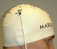
You may want the individual to wear a swimming cap during
registration and TMStimulation, so you can mark scalp and
cortical landmarks.
- It is best to use the subjects original MRI scan.
Scientists often 'normalize'
scans to match a generic brain shape and size. These
transformations (particularly the nonlinear transforms)
can hinder accurate MRIreg registration. Even if you do
want to work out your locations in normalized space, it
is better to compute your coordinates on the original MRI
scan. Later you can conduct normalization and use the
computed transforms to transfer your MRIreg coordinates
to normalized coordinates.
- Magnetic tracking is not the only way to compute spatial
location. There are also RF based (e.g. Polhemus Isotrak)
mechanical (e.g. Surgeon Arm, FARO Technologies) and
optical (e.g. Polaris, Radionics, IGT Pixsys) trackers.
The optical trackers allow position to be collected
during TMS sessions, allowing scientists to better gauge
wand location and wand. In addition, by using more than
one sensor, one can compute the wand angle, again better
estimating the location of stimulation. For more details,
please see Paus (1997), Neuropsychologia, 37, 219-224.
Well-funded scientists may want to consider the Polaris
(Northern Digital) infra-red tracking device combined
with
Brainsight,
LocalLite, or
ANT Visor
software. However, many labs have the
inexpensive Fastrak, miniBird or Flock-of-Bird systems,
allowing MRIreg to play a role as a cheap and cheerful
solution. Also, you may want to examine the
Neural Navigator (NeNa).
- The maximum range for a miniBird or Flock of Birds is 36
inches (with a standard transmitter). Therefore, all
measurements should be conducted within 36 inches of the
transmitter. It is important to remember that the
distance from the transmitter is a sphere - not a cube.
Therefore, the sensors will typically go out of range
before any of the dimensions (X, Y or Z) have reached
their maximum value.
- My neuroanatomy atlas is
a useful guide for identifying cortical landmarks,
including the motor cortex.
- Bonus software - the MRIreg download also includes Matlab code for viewing and
recording (in Brain Vision Analyzer format, which you can import into EEG lab) the
Ascension Flock-of-Birds, Mini-MBird and trakSTAR.
Click here to see the Matlab script.
- For Ascension Bird systems:
- You should have a cable connecting the serial
port of your computer to the Bird system (this is
a 9-pin male-to-female cable that directly
connects pins 2to2, 3to3 and 5to5). Important
note: if you use a standard serial cable pin #7
needs to be removed otherwise a signal is sent to
the bird resetting it that precludes any
recordings.
- Make sure you have the DIP switches on the back
of your flock-of-birds system set up correctly. The current version
of MRIreg defaults to 115,200 bps, so you should set switches 1,2,3 and 7 ON,
and have the other switches off.
If you are using the obsolete versions of MRIreg, it defaulted to 57,600 bps.
For a 57,6000 bps setup, you should set switches
1,2 and 7 ON, and have the other switches OFF.
- You can use a Ascension miniBIRD instead of the flock-of-birds.
This uses the same DIP switch settings. However, the miniBIRD does not work with all serial ports.
A solution is to remove pin 7 from the serial port cable used to connect the miniBIRD to your computer.
With this modification, the miniBIRD will work with MRIreg (though the cable may not work with other equipment).
- This software works with the Ascension trakSTAR.
Simply connect the RS-232 port of your trakSTAR to your computer's serial port and make sure
MRIreg is set for 115200 bps communications (the only speed supported by the trakSTAR). Note
that the smaller trakSTAR sensors have a very small sensitivity region (as shown in the image below).
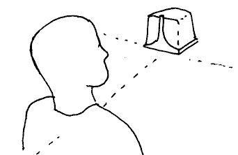
- The sketch above shows the correct location of
the FOB base unit with respect to the head.
Coordinates are mirrored in each of the base
unit's hemispheres, so it is important that all
scalp coordinates are located within a single
hemisphere of the base unit.
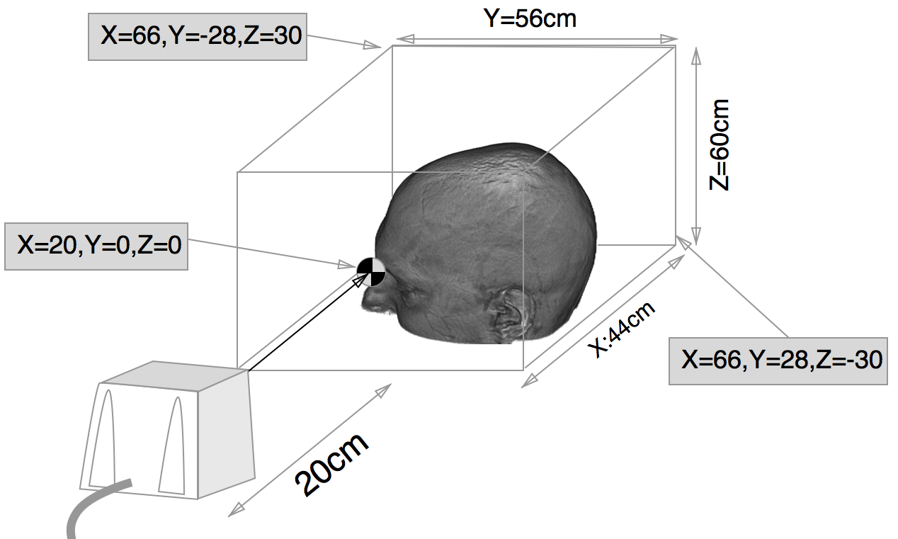
This figure shows the small bounding box of the trakSTAR with model 800 sensors. See
"Performance Motion Box" section of the trakSTAR manual.