| Experimental control using a PC |
This page describes pretty obsolete techniques - I have a new page that describes modern techniques that will work with modern hardware. All my experimental data are collected on IBM compatible personal computers (PCs). PCs were not originally designed for running real time programs and so difficulties with timing, precise video display, digital input (e.g. manual responses from buttons), analog input (such as an eye monitor), and digital output (controlling external devices such as LEDs, solenoids and speakers) are inherent with these machines. The usual approach to these problems is to use expansion cards with dedicated timers, analog-to-digital conversion (ADC) and digital input/output lines. However, these cards are expensive and usually require a bulky desktop computer. This appendix describes a number of software and hardware techniques which will work on any PC running MS-DOS (multi-tasking environments are inherently poor for real time tasks, and the timer described here is not compatible with Microsoft Windows). Using these techniques, a laptop PC can be an inexpensive, powerful and portable experimental data collection system.
However, while the routines and hardware described in this appendix are useful for data collection with a PC, careful programming is also required. For example, saving data to hard disks can cause long interrupts (delays where all processing is halted) which can have severe effects on the timing of experiments. One solution (which was employed in all of my experiments) is that data is saved to the hard disk only between blocks (with the data files being opened, written and closed at the end of each block).
The IBM has one timer which is easily accessible through software - the so-called 'time-of-day' clock. Unfortunately, in standard operation this timer is only updated every 55 msec, a temporal resolution which is unsuitable for most reaction time paradigms. Since the PC's introduction, a number of ingenious techniques have been used to improve timing routines. Unfortunately many of these algorithms can have serious side-effects on the performance of the computer's date setting, peripheral devices and speed of the computer (see Graves & Bradley, 1991 for a review). For my experiments, I used an algorithm reported by Bovens & Brysbaert (1990) which avoids these problems. Essentially, their algorithm sets the timer to operate in a countdown, rather than square-wave mode of operation, as depicted schematically in Figure A1. While the programmer can read the timer chip directly (which is updated more than 18 times each msec), the standard system timing interrupt signal is only given at each clock upbeat, which occurs at the same 55 msec interval as in normal operation, and therefore the computer's time, date and overall system performance are unaffected. Rather than describe this algorithm in detail, I refer readers to their article. Careful implementation of their algorithm can allow accurate timing for any interval up to 24 hours (software routines should be sensitive to the fact that the timer is reset at midnight each day). Note that these timing routines are not compatible with Microsoft Windows. Windows does have its own high-resolution timer; however, programs which attempt real-time data collection should avoid multitasking environments (such as Windows) altogether.
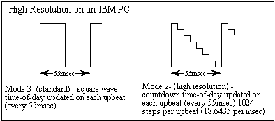
Figure A1.
Using the built in video on a PC for presenting experimental displays can be a challenging task. Different video cards use proprietary video standards, and typically software drivers for controlling these new video modes are only available for multitasking operating systems such as Windows (which are inherently ill-suited for controlling real-time data collection). Therefore, programmers who want to create portable programs (i.e. which can be used with any PC, regardless of video adapter) for MS-DOS must use the aging VGA-standard video modes (which are supported by all modern video cards). The typical VGA mode (mode 12h) provides 16 colors at a resolution of 640x480 pixels with a 60 Hz refresh rate (i.e. each frame is presented for 16.7 msec). However, the VGA standard has two modes of particular interest to programmers trying to develop displays with accurate video control. Many of my experiments use VGA-medium (mode 10h), which displays 16 colors at 640x350 with a 70 Hz refresh rate (14.4 msec per frame). Importantly, this mode splits the video memory into two identical segments ('pages'), either one of which can be displayed during any video retrace. This allows 'page-swapping', where one image can be generated while another image is being viewed. Smooth animation can be achieved if this page-swapping is synchronized with the video retrace signal (a process which will be described later).
A second video mode is also available which is useful for visual experiments: VGA mode D which displays up to 16 colors at a rather blocky 320x200 pixels with a 70 Hz refresh rate. Because of the low resolution, this mode is rarely used. In fact, most common programming environments do not provide drivers for this mode. Yet this mode provides 8 pages of video, allowing a whole sequence of displays to be generated before a trial begins, and then these images can be presented in very rapid succession independent of computer performance. Because all of the displays can be generated before the initiation of each trial, the hardware can be devoted to accurately monitor external devices (collecting eye position information and/or accurately timing manual responses).
For scientists seeking very rapid refresh rates, Spitczok von Brisinski (1994) has developed a number of custom high-refresh rate VGA video modes, and he distributes the computer code free of charge. Rather than changing the retrace rate by using multisyncing monitors and specialized video cards, he reduces the number of video lines which are drawn in each vertical retrace. For example, he reports a 640x100 pixel mode which scans at 289 Hz, a mere 3.4 msec per display! In theory, his code is compatible with virtually all PC computers which have CRT displays (LCDs switch too slowly to make such techniques practical). In practice, performance varies with hardware, and because VGA monitors are not designed for refresh speeds above 70 Hz, these modes may potentially cause permanent hardware damage.
Finally, there are DOS drivers which allow Turbo Pascal and Turbo C code to take advantage of higher resolution displays. Jordan Hargrave's shareware Super VGA drivers allow screen resolutions up to 1280x1024 with color depths up to 24 bits. The 16-color 800x600 and 1024x768 modes allow page swapping with most modern video cards (including most cards built into laptops). Hargrave's drivers use the same graphics calls as the standard Borland drivers, allowing for rapid porting of software to the new drivers. Genus Micro's professional driver's have a number of powerful routines which allow high resolution timing, display of PCX format images and high resolution screens.
It is vital to synchronize visual displays with the monitor's retrace signal. This allows an entire image to be presented in the same horizontal retrace, and ensures that all components of an image were presented for the same duration. During each refresh cycle, the electron beams (for a CRT) begin at the upper left corner, and then draw each line from left to right. When the beams is finished scanning the last (bottom) line, a vertical retrace signal is generated and the beams return to the top of the screen to begin a new cycle. Optimally, new displays should be presented during the vertical retrace, ensuring that the entire video image is presented during a single cycle. The procedure SyncWait (see the code appendix) presented below delays processing until the next retrace cycle, allowing accurate presentation of visual displays (Dlhopolsky, 1989).
One should bear in mind that standard CRTs (desktop monitors) pulse light very briefly during each display - even an apparently white screen spends most of each cycle completely black. On the other hand, LCD screens switch on and off very slowly.
For most purposes, input on a PC can be accomplished using the keyboard. However, keyboard responses are inherently inaccurate (average delay, 18.5 msec with an error of ±7.5 msec, see Segalowitz & Graves, 1990), and the bulky keyboard can be an unsuitable input device. There are three solutions to this problem. First, the two buttons on a joystick can be used, as the joystick port is read directly, giving excellent timing accuracy. The state of the game port can be determined by reading Port 201 Hex (in pascal, the function lval := port[$201] will put the current status of the joystick buttons into the integer variable 'lval'). A second solution is a serial mouse (which uses a D-shaped connector, rather than a PS/2 mouse which uses a round connector and has much poorer temporal resolution), which can be scanned with excellent accuracy (Segalowitz & Graves, 1990, report a delay of 31±2msec), at least as long as the mouse is not required to send motion signals as well (the ball should be removed from the mouse during experiments). Crosbie (1990) has presented Pascal code for monitoring the status of the mouse.
Several of my own experiments implemented a third solution: custom key switches were directly read from the input lines of the serial port (as described by Morris, 1992, p. 460). The serial port has four independent input lines, allowing up to four digital response keys. A schematic is given in Figure A2. When the experimental program launches, it must initialize the serial port for reading the input lines, which can be accomplished in Pascal with the command port[$3FC] := 1. After that, the command lval := port[$3FE] and 240 will put the current status of the buttons attached to the serial port into the integer variable 'lval'. For example, if the value 16 is returned, only the button connected to pin 8 is closed (as shown in figure A2, pin 8 has a value of 16), while a value of 80 indicates that the buttons connected to pins 8 (value 16) and 9 (value 64) are depressed.
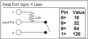
Figure A2.
If both the game port and serial port are unavailable (e.g. the serial port is linked with a touch screen or ASL 5000 eye monitor), the parallel port can also supply four digital inputs. Dalrymple-Alford's (1992) design is shown the lower right quadrant of Figure A3. The state of four micro switches (sw1-sw4 in the diagram) are read independently through the parallel port. Before the status of the switches can be read, the port must be initialized by writing 244 (hex F4) to the parallel port input/output address (you only need to do this once, when your program starts). The address of the parallel port input can be found by calling the procedure firstLPT (see the source section). The, the pascal code for initializing the parallel port inputs would be port[kOutPort] := 244 (where kOutport is usually 890, but may vary depending on your computer's configuration, note that you write to the base address plus two). Normally, these pins are used for outputs, but after writing the value 244 to this address, the status of the microswitches can be read accurately. Thereafter, reading from the 'output' address will tell you the status of the microswitches. The code lVal := (Port[kOutPort] and 15) will return the byte variable 'lVal' set to a number between 0 and 15. Pins 1, 14, 16 and 17 have the values 1, 2, 4 and 8 respectively. Therefore, if (Port[kOutPort] and 15) returned the value 10, it would indicate that the switches connected to pins 14 and 17 (values 2 and 8) were depressed. Note that this input option uses the same lines as theanalog input design I will describe later, so the two can not be used concurrently (unless modifications are made).
A final input design is presented in the top half of Figure A4. This option allows 8 inputs to be read with millisecond accuracy. The design employs a 74HC165 serial-latch input register which reads 8 digital inputs simultaneously and then reports the status in a serial binary stream. Pascal code for reading this design is presented in the code section (the 'inputs' function). For even more digital inputs, several 74HC165's can linked by 'cascading' the serial out pin of one chip to the data pin of the next chip.
Digital
Output ![]() Return
to Index
Return
to Index
Typically, dedicated output cards are used to control digital input/output functions on PCs. Unfortunately these cards are expensive and (typically) require a bulky desktop computer. Yet, the parallel port which is standard on any PC can be used for controlling up to 12 outputs. Eight of these output lines are all controlled through the same output port, allowing convenient independent control of 8 devices. The output system which I use is based on that of Markham (1993), though substituting the 74LS126 (non-inverting output driver) for the 74LS125 (inverting output driver). As shown in the Figure A3 below, pins 2-9 of the parallel port (parallel port pins are indicated by a number enclosed in a 'D' shape) drive relays A-H. Note that the parallel port's ground (any pins 18-25) are connected to the circuit ground. I use RS 817-050 5 volt relays (which come in a compact package and can support up to .5 amps each).
Note that my design also employs the 7805 voltage regulator. The 7805 provides a stable 5 volts when supplied with 8 through 18 volts of power. This allows the output controller to be powered with batteries. Battery power maximises portability and allows the IO system to be used in a hospital environment. I use eight AA size (aka R6, 1.5 volt) batteries to power the system. Because the 7805 is an inline package it is easy to confuse pin 1 with pin 3. When the 7805 is viewed from the side, with the designation markings facing the viewer (and the metal heat sink towards the back), pin 1 is the leftmost pin. More details of the power supply can be found at www.hut.fi/Misc/Electronics/circuits/psu_5v.html In my design, the batteries also supply 12 volts (via the relay's) to the solenoids and LEDs which I am switching.
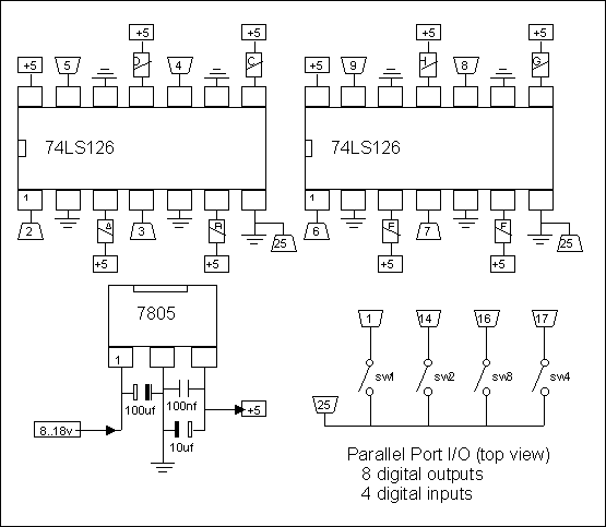
Figure A3.
Software control of this interface is very straightforward. An eight bit (0-255) value is written to the parallel printer port (usually port[$378], port[$278] or port[$3BC] if the printer port is set to an alternate address, the pascal code 'FirstLPT' listed in the appendix will automatically find the correct address), each bit of this value controls one of the 8 relays. For example, Port[$378] := 0 switches off all of the relays, while Port[$378] := 255 switches on all of the relays, and Port[$378] := 9 sets first and fourth relay on and turns off the other relays (9 = 1 (first bit) + 8 (fourth bit)). In this way, each relay can be independently controlled.
Figure A4 shows a more sophisticated parallel port input/output design which allows 16 digital inputs. The design utilises the 74HC595 serial latch output driver. Each '595 controls eight relays. The code section's Pascal procedure 'Outputs' accepts two byte values (lL and lH) which set the relays. The byte value lL controls the eight relays connected to the first '595 (e.g. a value of 0 turns off all of the relays, 255 turns all of the relays on, 129 turns on the first (bit value of 1) and eighth relay (it value of 128)). Likewise, the value lH controls the relays connected to the second '595. For more outputs, additional '595's can be linked together by connecting the serial out of one chip to the data in of the next chip.
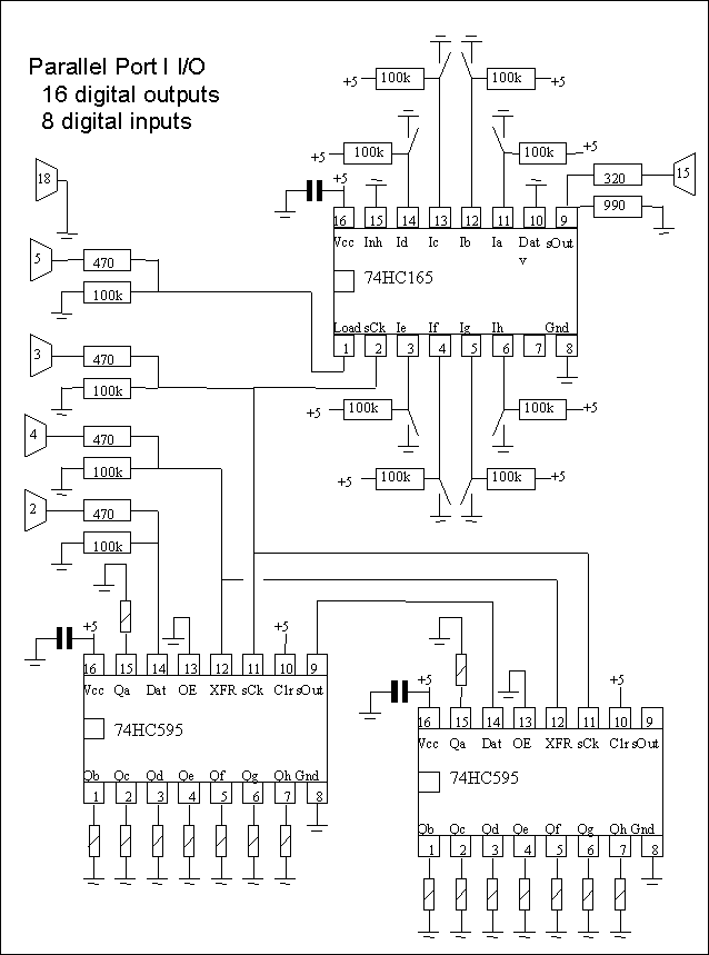
Figure A4.
Several of my experiments relied on using an eye movement monitor. This section describes a simple 12-bit Analog to Digital Converter (ADC) which can be read serially, requiring only three lines of the parallel port (one input and two output), thereby allowing the use of 8 lines for digital output. This ADC measures voltages between -5 and +5 volts, suitable for most eye monitors (the EyeTrac 210's -3 to +3 volt output as well as the -5 to +5 volt output of the Skalar IRIS 6500). The MAX176 ADC chip and the op-amp (LF412) should each be decoupled with a 100 nF capacitor bridging the V+ and V- (as shown in the diagram). This design can be created with inexpensive components, and the power supply can be used for both this ADC as well as the relays described in the previous section.
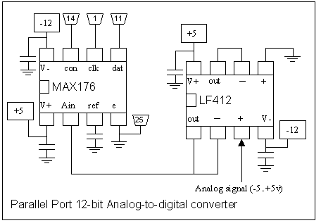
Figure A5. Note that pins 5,6,7 of the MAX176 are connected to pins 11, 1 and 14 of the computer's parallel port, respectively.
The operation of the MAX176 is described by Xia (1996), along with C software routines. My own pascal code 'serial12' for reading the ADC is given below. The software function Serial12 will return a value between 0 and 4095 depending on the analog input.
Users of the ASL210 or ASL310 eye tracking system can connect the control unit's in-built ADC to the parallel port. The diagram below the pin out to configure the connection. My XGen software will read the eye monitor if set for 'Parallel 8-bit v2'.
| Eye Tracker (Left) | Eye Tracker(Right) | Computer | Function |
| 16 | 2 | 1 | D0 |
| 15 | 1 | 14 | D1 |
| 13 | 17 | 16 | D2 |
| 14 | 18 | 17 | D3 |
| 6 | 10 | 13 | D4 |
| 5 | 9 | 12 | D5 |
| 3 | 7 | 10 | D6 |
| 4 | 8 | 11 | D7 |
| 23 | 22 | 3 | Data Request |
| 12 | 11 | 13* | Data Ready |
| 24 | 24 | 18-25 | Gnd |
The computer can either be connected to the left or the right eye's output (shown in the 1st and second column, respectively). With this setup, you can only record one channel at a time (i.e. your cable should be made to read only from the left eye or only from the right eye).The pascal function 'parallel8' will (in the appendix) read the output of an ASL 210/310. The function will return a value between 0 and 255 depending on the eye position. Note that the pin connection for 'Data Ready' has changed from 15 to 13 from my older 'parallel8' design (allowing use of the serial digital input device illustrated in figure A4).
Const
{these variable constants keep the addresses of the parallel
port}
kBasePort: integer = 888;
kInPort : integer =889;
kOutPort : integer = 890;
procedure
FirstLPT;
{this procedure finds the first available parallel [aka LPT]
port}
{use this to initialize the addresses for kBasePort,
kInPort,kOutPort}
var
lLPT: integer;
lInc, lVal: word;
begin
{LPT address stored from 400-407 }
lLPT := 0;
for lInc := 3 downto 0 do begin
lVal := (mem[0000:($409+lInc)] shl 8)+mem[0000:($408+lInc)];
if lVal <> 0 then
lLPT := lVal;
end;
kBaseLPT := lLPT;
kInPort := kBaseLPT + 1;
kOutPort : kBaseLPT + 2;
end;
Procedure SyncWait;
{this procedure waits for the next screen refresh signal}
var a: byte;
begin
repeat
a := Port[$3DA] and 8;
until a < > 0; {if currently cycling, wait until new cycle
starts}
repeat
a := Port[$3DA] and 8;
until a = 0; {repeat until new cycle starts}
end;
Function Inputs: byte;
{this function reads the state of 8 digital inputs connected to a
HC165}
{the status of the 8 inputs is returned as a value 0-255}
{assumes firstLPT has been called to set base/in/out setting}
const lkInit = 0;
lkOnPulse = 8;
lkOffPulse = 10;
var
lInc, lVal, lV,lBit: byte;
begin
port[kBasePort] := lkInit; {shift/load down -convert}
lVal := 0;
for lInc := 1 to 4 do begin
port[kBasePort] := lkOnPulse; {clock up transition sends
data/shift hi stops conv}
if (port[kInPort] and 8) = 8 then
lBit := 0
else
lBit := 1;
port[kBasePort] := lkOffPulse; {clock up transition sends data,
shift hi stops conv}
lVal := (lVal shl 1) + lBit; {shr=reduce/shl = larger}
end;
Inputs := lVal shl 4;
end;
Procedure Outputs(lL,lH: byte);
{this procedure switches 8 digital outputs connected to two
HC595's}
{the byte lL controls the 8 relays connected to the first 595}
{the byte lL controls the 8 relays connected to the second 595}
{assumes firstLPT has been called to set base/in/out setting}
var lRep,lVal : integer;
lLo, lHi: byte;
begin
if (kLEDport <= kMaxPort) and (kLEDport <> 0) then
Port[kLEDport] := lL;
if (gPort2 <= kMaxPort) and (gPort2 <> kLEDport) and
(gPort2 <> 0)then
Port[gPort2] := lH;
if (kLEDport <= kMaxPort) and (gPort2 <= kMaxPort) then
exit;
if kLEDport > kMaxPort then
lLo := lL
else
lLo := 0;
if gPort2 > kMaxPort then begin
lHi := lH;
gLastHi := lHi;
end else
lHi := 0;
lVal := 128;
for lRep := 8 downto 1 do begin
if (lHi and lVal) = lVal then begin
Port[kBaseport] := 1; {on bit}
Port[kBaseport] := 3; {clock on}
end else begin
Port[kBaseport] := 0; {off bit}
Port[kBaseport] := 2; {clock off}
end;
lVal := lVal shr 1; {shr=reduce/shl = larger}
end; {for lrep}
lVal := 128;
for lRep := 8 downto 1 do begin
if (lLo and lVal) = lVal then begin
Port[kBaseport] := 1; {on bit}
Port[kBaseport] := 3; {clock on}
end else begin
Port[kBaseport] := 0; {off bit}
Port[kBaseport] := 2; {clock off}
end;
lVal := lVal shr 1; {shr=reduce/shl = larger}
end; {for lrep}
Port[kBaseport] := 4; {XFR}
Port[kBaseport] := 6; {clock XFR}
Port[kBaseport] := 0;
end;
function Serial12: word;
{returns a value 0-4095 for the voltage at the 12-bit
analog-to-digital converter}
var
lLoops, lVal:byte;
l12bit: word;
begin
{MAX176 12-bit ADC - line 1 = CLK, line 2 = CONVSTART, both
INVERTED}
port[kOutPort] := 3; {CLK lo, CONV lo}
port[kOutPort] := 2; {ClK hi}
port[kOutPort] := 0; {both hi}
port[kOutPort] := 1;
port[kOutPort] := 3;
port[kOutPort] := 2;
port[kOutPort] := 3; {clock MSB}
port[kOutport] := 2;
lVal := Port[kInPort];
if lVal > 127 then {MSB (sign bit) is inverted}
l12Bit := 1
else
l12Bit := 0;
for lLoops := 1 to 11{7} do begin {read next 8 bits}
port[kOutPort] := 3; {clock out next bit}
port[kOutport] := 2;
lVal := Port[kInPort];
if lVal > 127 then {invert}
lVal := 0
else
lVal := 1;
l12Bit := ((l12Bit) shl 1) + lVal; {old value * 2 + new bit}
end;
Serial12 := (l12Bit) {shr 4 reduce};
port[kOutPort] := 3; {inverted, set 1 lo, 2cs lo}
end;
function BitSet
(pInvert:boolean; pV, pBit: byte): byte;
begin
if pInvert then begin
if (pBit and pV) = pBit then BitSet := 0
else BitSet := pBit;
end else begin
if (pBit and pV) = pBit then BitSet := pBit
else BitSet := 0;
end;
end;
function Parallel8Bit: byte;
{uses function 'BitSet'}
var l8Bit, lVal, lWaitFlag : byte;
begin
port[kEMOutPort] := $F4; {initialise inputs}
Port[kEMBasePort] := 16{2} {hold data}
repeat until ((port[kEMinport] and 8) <> 8); {will hang if
EM not connected: use timeout}
lVal := Port[kEMOutPort] and 15; {now an input port}
l8Bit := BitSet(false,lVal,1);
l8Bit := BitSet(false,lVal,2)+l8Bit;
l8Bit := BitSet(true,lVal,4)+l8Bit;
l8Bit := BitSet(false,lVal,8)+l8Bit;
lVal := (Port[kEMInPort] and 240);
l8Bit := BitSet(true,lVal,16)+l8Bit;
l8Bit := BitSet(true,lVal,32)+l8Bit;
l8Bit := BitSet(true,lVal,64)+l8Bit;
l8Bit := BitSet(false,lVal,128)+l8Bit;
Port[kEMBasePort] := 0; {turn off data hold}
Parallel8Bit := l8Bit;
port[kEMOutPort] := 0; {inverted, set 1 lo, 2 hi}
end;