| Volume Rendering the Cortex |
| Index | 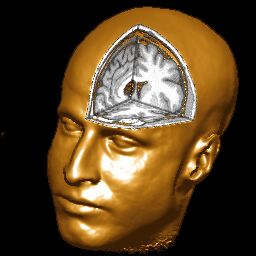 |
Introduction Return to Index
This page describes how to create volume renderings using my free MRIcro software. You can learn a lot about the brain by viewing axial, coronal and sagittal slices. However, it is often useful to display lesion location on the rendered surface of the brain. Just as each individual has unique finger prints, each brain has a unique sulcal pattern. SPM's spatial normalization adjusts the size and alignment of the MRI scan, but it does not deliver a precise sulcal match -such an algorithm would create many local distortions (just as an algorithm that attempted to normalize fingerprints from individuals with very different patterns would require many distortions). Volume rendering allows the viewer to grasp the sulcal pattern of the brain, and see lesions in relation to common landmarks. A second advantage for displaying a lesion on a rendered image is that you can specify how 'deep' to search beneath the surface to display a lesion, and in this way you can show the cortical damage without the underlying damage to the white matter Note that only showing lesions near the brain's surface can also be misleading, as it can hide deeper damage. Therefore, it is often best to present surface renderings in conjunction with stereotactically aligned slices.
There are two popular ways to render objects in 3D. Surface rendering treats the object as having a surface of a uniform colour. In surface rendering, shading is used to show the location of a light source - with some regions illuminated while other regions are darker due to shadows. VolumeJ is an excellent example of a surface renderer. The benefit of surface rendering is that it is generally very fast - you only need to manipulate the points on the surface rather than every single voxel in the image. On the other hand, volume rendering examines the intensity of the objects. So darker tissues (e.g. sulci) appear darker than brighter tissue. Finally, hybrid rendering allows the user to combine these two techniques - first computing a volume rendering and then highlighting regions based on illumination. For example, my software can create volume, surface or combined volume and surface renderings. The images created by MRIcro below illustrates these techniques. The left-most image is a volume rendering, the middle image is a surface rendering, and the image on the right is a hybird.

Surface rendering is by far the most popular approach
to rendering objects. One reason for this is that surface
rendering can be much quicker than volume rendering (as
only the vertexes need to be recomputed following a
rotation, while in volume rendering every voxel must be
recomputed). However, surface rendering typically has
several disadvantages compared to volume rendering:
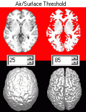
The third point is illustrated on the image on the right. Note that with a high air/surface threshold is required to show nice sulcal definition in the surface renderings. However, at these high values the gray matter has been stripped from the image. In contrast, low signal information enhances the definition of sulci for volume renderings. |
 |
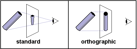
Most rendering tools add perspective: closer items appear larger than more distant items. Perspective is a strong monocular cue for depth, so this technique creates a powerful illusion of depth. However, in some situations, it is helpful to have perspective free images ('orthographic rendering'). Orthographic rendering has a couple of advantages: it it can be quicker and it can allow a region to remain a constant size in different views. MRIcro is an orthographic renderer.
One word of caution: Be careful about judging left and right with rendered views. My software retains the left-and right of the image. This is particularly confusing with the coronal view when the head is facing toward you. When we see people facing us, we expect their left to be on our right. With my viewer, their left is on your left.
Installing MRIcro Return to Index
The main MRIcro manual describes how to download and install MRIcro. The software comes with a sample image of the brain.
Creating a rendered image Return to Index
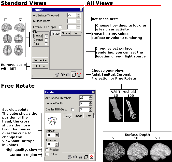
Rendering an image with MRIcro is very straightforward. Load the image you wish to view (use the 'Open' command in the file menu). Finally, press the button labelled '3D'. You will see a new window that allows you to adjust the air/surface threshold (which selects the minimum brightness which will be counted as part of your volume) as well as the surface depth (how many voxels beneath the surface are averaged to determine the surface intensity).
| Most rendering tools require very high quality scans (such as the MRI scan above, which came from a single individual who was scanned 27 times). As noted earlier, surface rendering tools in particular have problems with the low resolution or average contrast images that are typically found in the clinic. Fortunately, MRIcro works very well with clinical quality scans. The figures on the right come from single fast scans from a clinical scanner (the whole MPRAGE sequences required 6 minutes with Siemens 1.5T). The image on the left shows a stroke patient. | 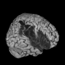 |
 |
The images above on the right shows a 'free rotation' with a cutaway through the skull. When you select the free rotation view, a new set of controls appear that allow you to select the azimuth and elevation of your viewpoint. A 3D cube illustrates the selected viewpoint - with a crosshair depicting the position of the nose. You can also use the mouse to drag the cube to your desired viewpoint. Finally, the 'free rotation' selection allows you to select a 'cutout' region to allow you to view inside the surface of the image.
Yoking Images Return to Index
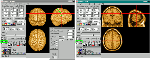
MRIcro is specifically designed to help the user locate and identify the ridges and folds (gyri and sulci) of the human brain. These are often difficult to identify given 2D slices of the brain. By running two copies of my software, you can select a landmark on a rendered view and see the corresponding location on a 3D image (as shown below, note you need to have 'Yoke' checked [highlighted in green]).
Overlays Return to Index
MRIcro can also display Overlay images - the figures below illustrate overlays. Typically, these are statistical maps generated by SPM, VoxBo or Activ2000 which show functional regions (computed from PET, SPECT or fMRI scans). I have a web page dedicated to loading overlays with MRIcro.
For volume rendering, you must then make sure the 'Overlay ROI/Depth' checkbox is checked. The number next to this check box allows you to specify how deep beneath the surface the software will look for a ROI or Overlay (in voxels). A small value means you will only see surface cortical activations/lesions, while a large value will allow you to see deep activations. For example, in the image on the left below, a skull-stripped brain image was loaded and then a functional map was overlaid.
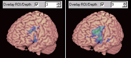 |
Left: functional results can be overlayed. Adjusting the depth value allows you to visualise surface or deep activity/lesions. |
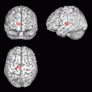
It is important to mention that MRIcro's renderings of objects below the brain's surface are viewpoint dependent. This is illustrated in the figures below. Both regions of interest (lesions) and overlays are mapped based on the viewer's line of sight. This is very different from mri3dX, which computes the location of objects based on the surface normal (essentially, mri3dX computes a line of sight perpendicular to the plane of the surface). Each of these approaches has its benefits and costs - both are correct, but lead to different results. Note that the location of subcortical objects appears to move when viewpoint changes in MRIcro. On the other hand, deep objects will appear greatly magnified with mri3dX. The rendered image of a brain (above, right) illustrates this difference. Here MRIcro is showing a very deep lesion near the center of the brain. The lesion appears at a different location in each image (SPMers call this a 'glass brain' view). A very deep object like this would appear much larger in mri3dX.
 |
 |
Brain Extraction Return to Index
In order to create high quality images of the brain's surface, you need to strip away the scalp. This is a challenging problem. My software comes with Steve Smith's automated Brain Extraction Tool [BET], (for citations: Smith, SM (2002) Fast robust automated brain extraction, Human Brain Mapping, 17, 143-155). BET is usually able to accurately extract brain images very effectively. To use BET, you simply click on 'Skull strip image [for rendering]' from the 'Etc' menu. You then select the image you want to convert, and give a name for the new stripped image. If you have trouble brain stripping an image, try these techniques:
Object Extraction Return to Index
The Brain Extraction Tool described in the previous
section is useful for removing a brain from the
surrounding scalp. How about removing other objects - for
example BET will not work if you wish to extract the
image of a torso from surrounding speckle noise. Most
scans show a bit of 'speckle' in the air surrounding an
object (also known as 'salt and pepper noise'. Most of
the time, you can simply adjust the MRIcro's 'air/surface' threshold to eliminate
noise. However, sometimes spikes of noise are impossible
to eliminate without eroding the surface of the object
you want to image. To help, MRIcro (1.36 or later)
includes a tool to eliminate air speckles.
|
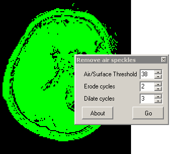 |
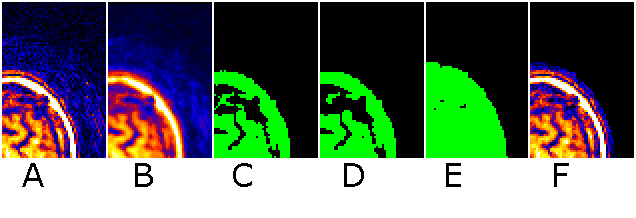
To understand the settings of this command, consider the
stages MRIcro uses to despeckle an image. First, consider an
image with a few air speckles (figure A below, note a few red
speckles in the air). MRIcro first smooths the image by finding
the mean of the voxel and the 6 voxels that share a surface with
it (B). This usually attenuates any speckles (a median filter
would be better, but is much slower). Second, only voxels
brighter than the user specified threshold are included in a mask
(C). Third, a number of passes of erosion are conducted (D).
During each pass, a voxel is eroded if 3 or more of its immediate
neighbors are not part of the mask. Fourth, the mask is grown for
the number of dilate cycles (E). During each dilation pass, a
voxel is grown if any of its immediate neighbors is part of a
mask. Note that any cluster of voxels completely eliminated
during erosion does not regrow - thus eliminating most noise
speckles. Finally, the voxels from the original image are
inserted into the masked region (F)
| The images to the right show how this technique can be used to effectively extract bone from a CT of an ankle. The right panel shows a standard rendering of the image using a air/surface threshold that shows the bone and hides the surrounding tissue. Note that the ends of the bones are not visible. On the right we see the same image after object extraction (threshold 110, 2 erode cycles, 2 dilate cycles). The extracted rendering appears much clearer than the original. | 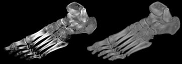 |
Maximum Intensity Projections [MIP] Return to Index
| So far this web page has described MRIcro's two primary rendering techniques: volume and surface rendering. However, MRIcro 1.37 and later add a third technique: the maximum intensity projection. This technique simply plots the brightest voxel in the path of a ray traversing the image. The result is a flat looking image that looks a bit like a 2D plain film XRay. This technique is typically a poor choice for most images. The exception is some CAT scans and angiograms. In this case, the MIP is able to identify bright objects embedded inside another object. The images at the right show an MR angiogram of my brain (this image shows an axial view of my circle of willis) and a CT scan of a wrist (note the bright metal pin). To create a MIP, simply select press the 'MIP' button in MRIcro's render window. | 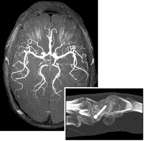 |
Sample Datasets Return to Index
Here are some large sample datasets. The CT scan is perfect for surface renderings, and allows you to change the air/surface threshold to either see the skin or bone as the image surface. This image demonstrates that MRIcro's rendering can be equally effective with CT scans. Additional images can be on the web. Some nice data sets are a knee, a skull (with EEG leads attached), a bonsai tree, an aneurysm, a foot, a lobster, a high resolution skull, a a fish, Virgo cluster, and a a teddy bear. All the images I provide for download here have had the voxels outside the object (typically air) set to zero (this improves file compression).
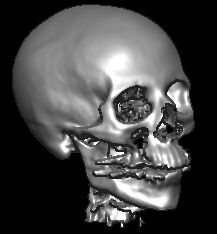 |
This CT scan is from the Chapel Hill Volume Rendering Test Dataset. The data is from a General Electric CT scanner at the North Carolina Memorial Hospital. I cropped the image to 208x256x225 voxels. Shift+click here to download (2.7 Mb). |
| A clinical-quality MRI scan of a healthy individual (1.5T Siemens MPRAGE flip-angle=12-degrees, TR=9.7ms, TE=4.0ms, 1x1x1mm). This image has 180x256x213 voxels. Shift+click here to download (3.4 Mb). Courtesy of Paul Morgan. |  |
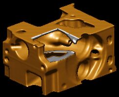 |
This is a 256x256x110 voxel CT of an engine. This is a popular public domain image. Shift+click here to download (1.5 Mb). |
| As well as CT and MRI scans, MRIcro can also render high resolution images from laser scanning confocal microscopy. The latest versions of MRIcro automatically read BioRad PIC and Zeiss TIF images. Shift+click to download this image of a daisy pollen granule from Olaf Ronneberger (0.5 Mb). | 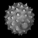 |
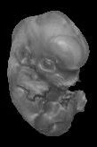 |
Shift+click to download this MRI scan from a mouse embryo taken 13.5 days post conception (0.5 Mb). For more details, visit the home page for this project. |
| Shift+click to download this MRI arterial angiogram of my brain's circle of willis (0.5 Mb). This scan was acquired with a 0.2x0.2x0.5mm resolution, then object extracted and rescaled to 0.4mm isotropic (to reduce download time). (3.0T Philips FFE flip-angle=20-degrees, TR=32.7ms, TE=3.4ms, '3DI INFL HR'). Courtesy of Paul Morgan (see his web page for movies of angiograms and other MRI scans). Amazingly, there is no artificial contrast. Also, note that the veins have been suppressed. | 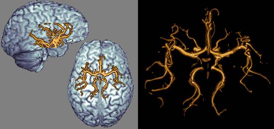 |
Acknowledgements Return to Index
Tom Womack devised the rapid surface shading algorithm and gave me a lot of tips (he also compiled the version of BET that I distribute). Krish Singh's brilliant mri3dX inspired me. Its ability to show viewpoint independent functional data makes it a complimentary tool for visualising the brain. Steve Smith's BET usually turns skull stripping from a tedious effort to an automated process. Earl F. Glynn developed the code for computing a matrix based on azimuth and elevation. This elegant tool allows the user to change their viewpoint without having to worry about gimbal lock problems or confusing controls. MRIcro does not use/require DirectX or OpenGL, for great articles on 3D graphics visit www.delphi3d.net.
Other renderers Return to Index
In addition to MRIcro, a number of freeware programs are available that can display rendered images of the brain (either surface rendering, which treats the surface as a uniform color, or volume rendering, which takes into account the brightness of the material beneath the surface). Both MRIcro and mri3dX inlude Steve Smith's BET software for extracting the brain from the rest of the image. For the other programs, you will first need to skull-strip your brain images (e.g. with BET or BSE).
| Name | Description |
| Activ2000 Windows |
Activ2000 for Windows can show functional activity on a surface rendering. |
| AMIDE Linux |
This Linux software can read Analyze, DICOM and ECAT images. |
| ImageJ
with the Volume Rendering plugin Macintosh, Unix, Windows |
Michael Abramoff has added volume rendering features to Wayne Rasband's popular Java-based ImageJ software. ImageJ can read/write analyze format using Guy Williams' plugin. |
| Java
3D Volume Rendering Macintosh, Unix, Windows |
Java based volume renderer. |
| Julius Unix, Windows |
Volume Rendering Software. |
| OGLE Linux, Windows |
Volume rendering of grayscale (continuous intensity) and RGB (discrete colours) datasets. Ogle is a nice tool for rendering MRI/CT scans. For example, to view the clinical MRI scan from my Sample Datasets section, you can double-click on its .ogle text file (the first time you open a .ogle file, you will have to tell Windows that you want to open these files with Ogle). Here is a sample .ogle file for the clinical scan. You can also try a different version of this software named ogleS. |
| MEDAL Windows |
Reza A. Zoroofi's freeware for Windows can create surface renderings of Analyze and DICOM images. |
| MindSeer Macintosh, Unix, Windows |
Java based volume renderer that can overlay statistical maps as well as venous/arterial maps. Can view Analyze, MINC and NIfTI formats. |
| mri3dX Unix |
Krish Singh's freeware, which runs on Linux, Mac OSX, Sun and SGI computers. A basic mri3dX tutorial is available. |
| Simian Linix, Windows |
looks like the future of volume rendering. Joe Kniss has developed this software that can take advantage of powerful but low cost GeForce and Radeon graphics cards. The Translucency approximation looks pretty stunning. |
| Space Windows |
Lovely interface with nice looking rendering. |
| Volsh Unix |
NCAR Volume Rendering Software. |
| VolRenApp Windows |
Volume and surface rendering. |
| Volume-One Windows |
This software can also use an extension for viewing diffusion tensor imaging data. |
| V^3 Windows, Linux, MacOSX |
Accelerated volume rendering (requires a GeForce video card). |
| ImageJ
with the Volume Rendering plugin Macintosh, Unix, Windows |
Kai Uwe Barthel has added volume rendering features to Wayne Rasband's popular Java-based ImageJ software. ImageJ can read/write analyze format using Guy Williams' plugin. |
| Voxx Windows |
Volume rendering tailored for confocal imaging (requires a GeForce video card, with fast hardware-accelerated rendering). Includes the ability to superimpose different image protocols of the same volume (e.g. with one protein-type shown in red and the other shown as green). |
| MITK Windows |
Medical Imaging Interaction Toolkit, developed by Dr. Tian and colleagues. |
| MVE - Medical Volume Explorer Windows |
fast volume rendering of Analyze and DICOM images. |
| BioImage Suite Windows, Macintosh, Linux |
This integrated image analysis package includes many useful tools. |
| MIVIew Windows |
MIview is an OpenGL based medical image viewer for NIfTI and DICOM images. |
| MRIcron Windows, Macintosh, Linux |
While my MRIcro software was designed for Analyze format images (SPM2 and earlier), MRIcron extends my software to support the NIfTI format (SPM5 and later). |
| IRCAD VR-Render Windows |
A useful volume renderer that allows you to adjust both the color and transparency for different tissue types. |
| MRIcroGL Windows |
My simple OpenGL volume renderer for NIfTI images. |