| |
Introduction
This
web page describes how to install and use my ezlog data
logging software. This software allows you to measure
when different events happened, allowing you to
synchronise the timing of different stimuli.
Specifically, my software is designed to get a detailed
report of when visual/auditory or tactile stimulation
occurred relative to brain images. By collecting
functional MRI scans that are sensitive to changes in
blood flow, we can identify the brain regions that are
involved with certain tasks. My software will measure the
time when each brain image was acquired as well as
logging the time of the stimulus that the participant
perceived. This tutorial is broken into four secions:
- Hardware: you need to create a cable that
connects your scanner and stimulus presentation
computer to a computer that will log the times of
stimuli and scans.
- Software: A quick introduction to my ezlog data
logging software for Windows.
- Notes: details for using this software
effectively.
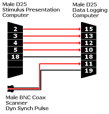
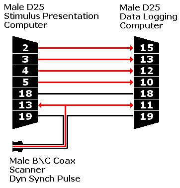
Hardware
You need to create a cable that can connect the
different devices that you wish to record. Each
device should be able to generate a TTL
(transistor-transistor logic) pulse. The diagram
on the right illustrates a cable designed to
connect the parallel ports of two computers
together, as well as connecting to a scanner.
This picture shows a coaxial connector plugging
into the scanner, matching the TTL output found
on Philips Intera scanners with system release 10
or later. Note that the stimulus presentation
computer sends outputs through pins 2..5, and
these are recorded on the input pins of the data
logging computer. In addition, note that the
0volt ground lines (shown in black) connect all
devices (on a computer's parallel port, pins
18..25 are all ground lines). |
 |
Advanced Hardware
Make sure your scanner is set up to generate pulses
with your EPI sequences. For Philips scanners, you go to
the 'Dyn' (Dynamic) page of the sequence protocol and set
the 'Dyn. Sync. Pulse' to TRUE. Note that this may
increase the acquisition time of your volumes (e.g. we
recorded the duration of each volume increased by 15ms).
The pulses generated by your scanner should have a
duration longer than 1ms. My software only checks the
parallel port every millisecond, so it will typically
miss very brief pulses. For example, by default the
Philips Intera generates a 0.05ms pulse. Furthermore, the
input to the parallel port needs to be an electrical TTL
pulse (not the optical pulse generated by modern Siemens
scanners). Therefore, you may need to build extra
hardware to connect your scanner to a PC (regardless of
whether the PC is running my software or something else
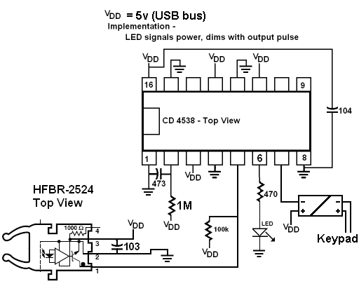
such as EPrime). Below are two very inexpensive circuits
I have built myself (they were designed by my dad, Bob
Rorden, Phil Moore suggested using the inexpensive
IF-D95T). These can be powered by a battery or a small
power supply. I am not responsible for any damage that
may result from other people's implementation of these
circuits. However, note that if correctly constructed
both designs allow the scanner to be electrically
isolated from your hardware. This should ensure that your
scanner can never be damaged by your PC. Specifically,
both circuits make sure that the signal between the
scanner and the PC is an optical pulse, not a direct
electrical signal. For example, if the scanner generates
an electrical signal, I use a PC815 photocoupler to
isolate the two systems. For these circuits, you should
connect the 'OUT' pin the data logging computer's pin 11
and the circuit ground to the data logging computer's pin
19 (as described in the previous section). With all
Philips scanners and Siemen's EPI scanner sequences prior
to 2002B you will want to use the circuit for an
electrical signal. For recent Siemens systems, you should
use the circuit for the optical signal. The Siemens
manaul 'Triggersignal outputs programmed by sequences'
includes more details, as well as an alternative circuit
for converting an optical pulse to a TTL pulse (my
circuit is less expensive and also lengthens the duration
of the optical pulse). An alternative Siemens optical circuit is described on the
University of Liverpool MARIARC website
Schematic for use with Philips scanners
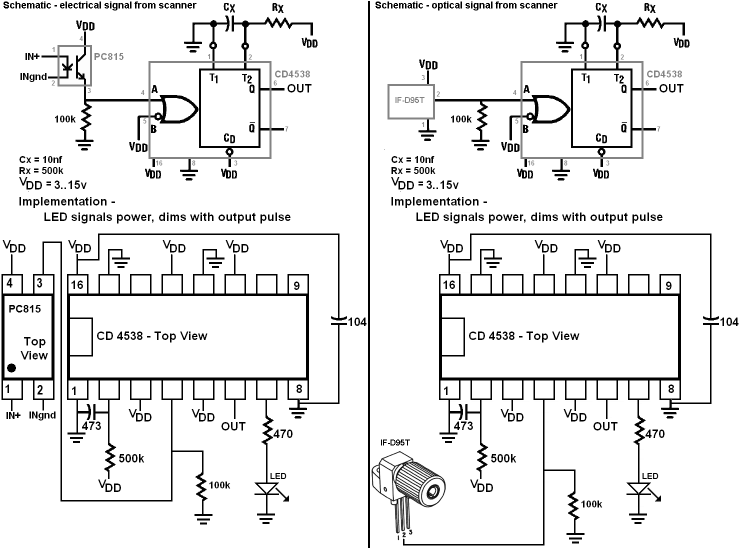
Schematic for use with Siemens scanners - signal from pin 6 can be used for TTL pulse to computer port or pin 7 can be used for a relay (note pin 7's pull down can provide more current than pin 6's push up).
Alternatively, you can set the scanner to generate
longer pulses. I do not recommend this solution:
increasing the scanner pulse length appears to decrease
the speed of acquisition (Philips Intera 10.3 software).
To change the pulse width generated by the Philips
Intera, open the 'Scan Utilities' button, select 'service
mode', select 'Control parameters' and adjust line 7: the
'DYN: Synch pulse duration (ms)'. You may need to log
into the scanner in 'GyroAcq' mode instead of the
'Intera' mode to make these changes.
Software
My ezlog software works with computers using the
Windows operating system and having a parallel port. The
software has been tested with WindowsXP, but should work
with Windows 95 and later. The software employs the
Windows API Multimedia Timer that should offer
millisecond accuracy on most computers. Because Windows
is a multitasking operating system, it is possible that
the software may ocassionally be off by a couple
milliseconds, but the resolution is fine for measuring
fMRI and behavioural data (the changes in blood flow
occur over seconds). You can download my software by shift+clicking here. Simply unzip
the file and run the software. Note that there are two
files: the application 'ezlog.exe' and the library
'inpout32.dll': these files should remain togehter in the
same folder on your hard disk. Double click on ezlog.exe
to launc the program.
The first time you run the program, check that the parallel port address is set correctly. From your Windows Device Manager find out the address of your LPT port. The device manager reports the address as hexadecimal, and my software expects the value as decimal. You can use the scientific mode of the Windows caluclator to convert between the two. For example, if your LPT port has address $378, the decimal value is 888. Launch ezlog and choose Setup/SetPort and enter the correct address. You should only need to do this once, the software should remember your port address.
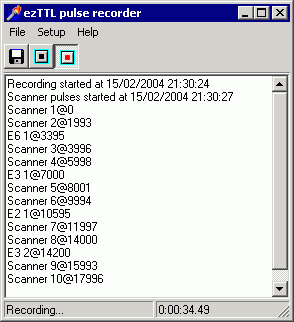
To start recording data, press
the red 'start recording' button. The status bar
on the bottom of the program's window will
initially report 'Recording... waiting for 1st
pulse'. As soon as the software begins detecting
TTL pulses from the scanner it will begin showing
the type of input and the time of input it is
receiving. The window on the right shows a brief
recording session: note that it registered pulses
from the scanner every 2 seconds (e.g. pulses at
0, 1993, etc milliseconds). Note that the
software also reports the onset of other events
that were reported by the stimulus presentation
computer (for example, it measured the 'E6' event
type 3395ms after the first scanner pulse. To
record a data sequence, you would want to follow
the steps below:
- Prepare your scanner.
- Prepare the experimental software and
have it ready to be triggered when the
scanner starts.
- Press the 'start recording' button on
ezlog.
- Start the scanner's fMRI recording.
- When the session is finished, press the
'Stop recording' button on ezlog.
- Press the 'Save to disk' button on ezlog
to store the event files.
|
 |
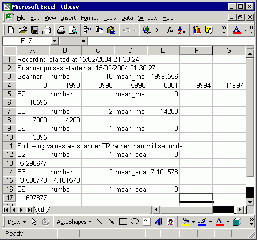
| My ezlog software will save data
in the '.csv' format (comma separated values).
You can view csv files with any text editor, or
you can open them with a spreadsheet, such as
Microsoft Excel or the OpenOffice spreadsheet.
The figure on the right shows the data for the
logging session illustrated above. For example,
row 4 shows that scanner pulses were recorded at
0, 1993, 3996... milliseconds. Row 3 summarises
the scanner pulses, noting that the mean time
between these pulses was 1999.556 milliseconds.
This value would be the 'interscan interval' you
would want to record if you were conducting an
SPM analysis. Note that events recorded from the
stimulus presentation computer are recorded both
in terms of milliseconds as well as scans. For
example, row 8 shows that 'E3' events were
recorded at 7000 and 14200 milliseconds. While
row 15 shows that these same events happened
after 3.5 and 7.1 scans had elapsed (the start of
the first scan is considered time zero). In
programs like SPM2, the timing of events is
typically coded in terms of the number of scans
that have elapsed. |
 |
Notes:
- My ezlog software can record up to 15 different
types of events from the stimulus presentation
computer (4 bits, with 0 being used to denote the
offset of an event).
- My software assumes that the data logging
computer has its parallel port at address 888
decimal (hex 378). To check the address of your
parallel port, right click on the 'My Computer'
icon on the desktop and select properties, click
on the 'Hardware' tab, click on the 'Ports' icon
and right click on the Printer port' icon to
select its properties. The 'resources' tab will
show you the 'I/O range' for the parallel port.
If this is not 0378-037F, you will want to
uncheck the 'use automatic settings' checkbox and
select a setting from the 'Settings based on'
pull down menu that cause the I/O range to be
0378-037F.
- By default, the TTL pulse generated by the
Philips Intera scanner is very brief (0.005ms).
Since my software only checks the parallel port
once per millisecond, you will want to increase
the dynamic synchronization pulse width. Contact
your Philips service people for details on how to
do this (it is easy, as the changes can be set in
software).
- You will also want to instruct your stimulus
presentation computer to send TTL pulses at the
onset and offset of each event. This will vary
depending on the software you use. For EPrime or
IFIS you have two options. The first option is
slightly more accurate and also slightly more
elegant. For both options, you will want to save
a value between 1 and 15 that reflects the
condition. I usually put this into the same list
that selects the stimulus and correct
response.For example, in addition to a column
labelled 'CorrectResponse', you will want a
column labelled 'PortOut' that has a different
value between 1 and 15 for each condition. Only
use ONE of the two following
techniques
- You need to know the LPT port address for the EPrime computer. You can find this out using the
Windows device manager. In the examples below I assume that this address is &H378 (hexidecimal 378; which is decimal 888). In Atlanta, our parallel port is &HE800 (hex E800).
- Change the properties of the object you
wish to log to reflect the TTL pulse you
want to record. For example, if you want
to have the ImageDisplay object named
'TargetImage' trigger a TTL pulse, you
could make the following changes:
- Create an 'Inline' event that
occurs before the stimuli are
presented.
- Add the following lines to the
inline code:
- TargetImage.OnsetSignalEnabled
:= true
- TargetImage.OnsetSignalPort
:= &H378
- TargetImage.OnsetSignalData
:=
c.GetAttrib("PortOut")
- TargetImage.OffsetSignalEnabled
:= true
- TargetImage.OffsetSignalPort
:= &H378
- TargetImage.OffsetSignalData
:= 0
- Add an inline code immediately before
your target is presented. Set this to
read "WritePort &H378, c.GetAttrib("PortOut")".
Create a second inline code after your
target and set this as follows: "WritePort &H378, 0".
Note the first inline code switches on
the TTL pulse, the second turns it off.
- You can also install my ezlog software on your
stimulus presentation computer. This allows you
to check that the cable is set up properly. Open
copies of ezlog on both computers, and select
'Test and defaults' from the 'Setup' menu on both
computers. When you click on the first four
Parallel Port Output checkboxes on the stimulus
presentation computer you should see the
corresponding changes in the 'Inputs' checkboxes
of the data logging computer.
- You can change the names for the different
events.By default, and in the illustrations
above, the 15 possible events are labelled 'E1',
'E2'...'E15'. However, it is probably easier to
give the events meaningful names like
'LeftImage', 'RightImage', 'TopImage'. To change
the event titles, open ezlog and select 'Test and
defaults' from the 'Setup' menu. You will notice
that there are 15 editable text boxes, initially
called 'E1', 'E2', etc. My software will remember
your labels between sessions. You can also make
different copies of the software with different
filenames (e.g. 'ezlog.exe', 'ezlog2.exe') and
each will store and remember different event
labels.
- Note that you can also start an EPrime experiment
using a TTL pulse from your scanner. This allows
you to synchronize the presentation of stimuli
with your scans. You could use the
"ReadPort" command. My BasicParallel experiment shows a simpler method:
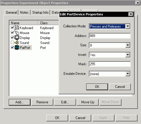
- Open your EPrime experiment, select 'Experiment' from the
'Edit' menu. Choose the 'Devices tab'. Press the 'Add' button and then
create a 'Port' device. You will want to set the Collection Mode to
"Presses and Releases", the Address to 889 (assuming that your parallel port is at address range 0378-037F hex [888-895 decimal], For example in Atlanta our address range is E800-E807 hex [59392-59399 decimal] so you in Atlanta use 59393 instead of 889), the size to 8, set "Invert"
to yes, the Mask to 255, and "Emulate Device" to none.
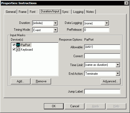
- At the start of your experiment you will want an
ImageDisplay or TextDisplay object that will pause until a scanner
pulse is detected. You will want to open this object's properties
window and choose the "Input/Duration" tab. Set the duration to
"(infinite)", the "End action" to terminate. For the Devices, add the
port you created in the step and set the allowable input for this
device to {ANY}. I also like to add a 'Keyboard' device, and set its
allowable input to {F6}. This allows you to start the study without a
pulse from the scanner by pressing Fn6 (identical to IFIS).
- If you want to use the
scanner signal to trigger EPrime as well as use
my datalogger, you will have to make a cable that
looks like this:
|